Have you ever looked at an aircraft or car and wondered how the stresses are distributed in the structure? I have, but maybe I am boring…..or maybe I am an engineer (hopefully the two are not synonymous!).
I was on a family visit to the Yorkshire Air Museum the other day and was reflecting on structural analysis, along with my 4 year old nephew (ok maybe I am boring, but it’s never too early to start learning!). They have a large collection of mostly modern aircraft, but with some older ones thrown in. It is at a military airfield, so the focus is on war planes, but there are several pre 1st World War ones there, and the beauty I find with them is that I can see the structure, either clearly displayed, or under the canvas.
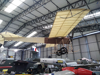
Modern structures can be hard to study. When I look at a modern monocoque structure, where the whole of the skin is stressed, I find it hard to understand the load paths. In the past it was much easier to see how a structure worked. When we had open truss structures, it was possible to see where the engineer had put the supports, and thus to see where the loads in the structure ran. The Blackburn Mercury that my son photographed is a prime example (Figure 1). Through the fabric you can see the supports in the tail section. Tiny frames take the tail loads and transfer them to the rest of the aircraft. Anything more and it would be tail heavy and would not fly.
Figure 1, Blackburn Mercury monoplane (and for plane geeks, a Gloster Meteor, Waco Hadrian glider and the tip tank of a Hunting Percival Jet Provost, for car geeks that is an Austin Champ under the Meteors tail, and one for the real history buffs, the black and yellow fuselage belongs to a Cayley Man Carrier replica)
I find those early aircraft so fragile, and yet people flew in them, of course many people died trying, but ultimately that is how working structures were created. One such early victim was Otto Lilienthal who is reputed to have said as he lay dying following a crash “Sacrifices must be made”.
Particularly in aircraft, as the weight was so critical,
nothing is superfluous and so if the designer puts something there then it is
needed, but racing cars have the same requirement, as lightness equals speed
and nimbleness. It is rumoured that Colin Chapman, founder of Lotus Cars would
design a full space-frame chassis then remove bracing until the chassis
collapsed and then put the last brace back in. This really kept with his
philosophy that can be stated as “simplify, then add lightness”, a quote often
attributed to him, but in fact in circulation before then, but it is a
philosophy that still influences Lotus car development to this day.
While it may seem odd to add in structural elements and then
remove them, it does mean that a light product is developed, and it helps us to
understand the design and construction of old aircraft.
There is another quote regarding aircraft design, which is “they don’t build them to crash, they build them to fly”. The meaning of this one is that we have to make them light or they won’t fly. It is no good making the strongest aircraft in existence if it can’t leave the ground. Again, the philosophy is clearly that lightness wins, and nothing unnecessary can be carried. Unfortunately, that means that aircraft do not survive well in crashes, but they wouldn’t fly if we made them stronger, although engineers and new materials can help with that.
So what?
Well, I want my students to understand structural design,
but if they can’t see the load paths, how can they understand that design? This
is particularly true in the early stages of their education, before they learn
detailed stress analysis techniques.
When I look at an old aircraft structure I can see where
stresses run and understand how the structure was developed. I am supervising a
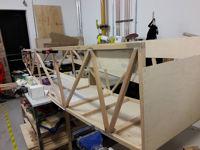
group of students as we build a Pietenpol Air Camper, and we can see directly
where the load paths are (Figure 2). We can see the main fuselage rails and the
bracing, the undercarriage load points, the wing loads that support the pilot
and co-pilot. Once the engine is attached, it will be on a mount that puts the
loads in to the crucial members and pulls the aircraft along, with the body
resisting the torque from the propeller. We can see where all those loads run,
we can understand the structure and we can learn a lot about vehicle
engineering. Indeed, we can easily calculate the loads and deformations using
simple beam theory to determine the strengths. Now where is my calculator?
Figure 2, side view of the fuselage of a Pietenpol Air Camper under construction.
I am certainly not against modern developments, but if we take a modern monocoque structure this is much harder to do. To optimise a monocoque, we will either need to trust to luck, or use some form of calculation approach such as finite element analysis to help us, my calculator is not really powerful enough to do the job. Indeed, this difficulty in seeing where the stresses run led to air disasters, and the failure of the first commercial jet airliner, the De Havilland Comet. In the early days of pressurised aircraft, and with the advent of new engines, the designers wanted a modern look, and decided to move away from round portholes for the hatches and windows, and instead use large square ones. Unfortunately, in the aircraft skin, these square corners led to stress concentrations, the effect of which was not known on the new monocoque structures. Several Comet mk1 aircraft crashed with lost of all on-board, which necessitated a return to ovoid windows, which are still universally seen on aircraft to this day.
Engineering is a skill that I want my students to learn, and
we can learn a lot from history, lots of what not to do, and also some of what
we can do. Understanding structures is fundamental to being an aircraft
engineer, so don’t forget to look at the old as well as the new. We still need
to “add lightness”, and computers can help us do that, but a good engineer
needs to know how it all works, because the computer doesn’t get sued when it
all goes wrong!

